The hillside neighborhoods of Merriman Valley and the steep bluffs overlooking the Cuyahoga River present fundamentally different stability challenges than the flatter terrain near Goodyear Heights, where ancient glacial lake deposits dominate the subsurface. This contrast in Akron’s topography means a standard approach to slope assessment simply doesn’t work. When a developer is eyeing a parcel in West Akron with a 25-degree incline, the analysis must account for the layered glacial till and the way water moves through those dense, silty clays after a heavy spring thaw. We see this pattern repeatedly in our laboratory: the same soil that holds firm during a dry August can lose significant shear strength when saturation levels rise, and that’s precisely why a thorough slope stability analysis must integrate both laboratory testing and field observation. Complementing the geotechnical investigation with in-situ permeability testing often reveals perched water conditions that standard borings might miss entirely.
A water table rise of three feet can reduce the factor of safety on an Akron glacial till slope by 30%—seasonal monitoring is not optional.
Process overview
Local context
The glacial stratigraphy beneath Akron often includes a discontinuous layer of water-bearing sand and gravel trapped between two till sheets, a condition that has contributed to several documented landslides along the Cuyahoga Valley escarpment over the past decades. When pore pressures build in this confined layer during prolonged wet periods—which are becoming more frequent with changing precipitation patterns in Northeast Ohio—the effective stress at the interface between the granular unit and the underlying clay drops precipitously. A slope stability analysis that does not explicitly model this interbedded drainage layer can overestimate the factor of safety by a dangerous margin. We’ve investigated sites where homeowners noticed tension cracks in their backyards after a single season of above-average rainfall, only to discover that the failure plane was propagating along precisely this stratigraphic boundary at a depth of 12 to 18 feet. The cost of ignoring these subsurface details is measured in foundation damage, retaining wall collapse, and in the worst cases, the loss of usable land area that no amount of remediation can fully recover.
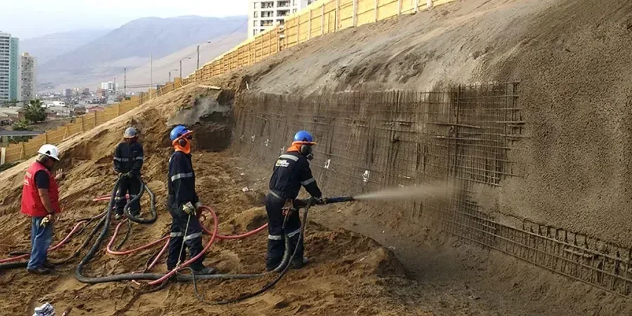
Visual overview
Reference standards
ASTM D4767-11 (2020): Consolidated Undrained Triaxial Compression Test for Cohesive Soils, ASCE 7-22: Minimum Design Loads and Associated Criteria for Buildings and Other Structures, Chapter 11, IBC 2024: International Building Code, Chapter 18 (Soils and Foundations), FHWA-NHI-05-123: Soil Slope and Embankment Design (Reference Manual), ASTM D2487-17e1: Standard Practice for Classification of Soils for Engineering Purposes (Unified Soil Classification System)
Additional services
Limit Equilibrium Stability Modeling
We use Spencer and Morgenstern-Price methods to evaluate circular and non-circular failure surfaces through the layered glacial deposits typical of Akron. Each model incorporates site-specific triaxial shear strength data, piezometric monitoring results, and the seismic coefficient required by ASCE 7-22 for the region. The output includes detailed cross-sections showing critical slip surfaces and corresponding factors of safety under both drained and undrained conditions.
Site Investigation and Laboratory Testing
The modeling is only as good as the input parameters, which is why our investigation program includes continuous sampling through the full depth of the potential failure zone. We perform Atterberg limits, grain size analysis, and consolidated-undrained triaxial tests on undisturbed specimens, all under our ISO 17025-accredited quality management system. The resulting strength envelope and pore pressure parameters feed directly into the stability calculations without relying on generic correlations from the literature.
Typical parameters
Quick answers
What triggers a slope stability analysis requirement in Akron?
The City of Akron’s building code, which follows the IBC Chapter 18, requires a geotechnical evaluation including slope stability analysis for any proposed construction on slopes steeper than 15% or where the planned cut or fill exceeds five feet in vertical height. Additionally, properties adjacent to the Cuyahoga River or its tributary ravines often fall under hillside development overlay zones with stricter requirements. Our reports are prepared to satisfy both the building official’s review and the Summit County Soil and Water Conservation District standards.
How long does a complete slope stability analysis take from start to finish?
A typical project timeline spans three to four weeks. The first week covers the field investigation: drilling, sampling, and piezometer installation. Laboratory testing—triaxial compression, Atterberg limits, and classification—requires ten to fourteen days due to consolidation and shear phases that cannot be accelerated. The final week is dedicated to modeling, report preparation, and peer review by our senior engineer. Expedited schedules are possible for smaller sites with simpler geology, though the triaxial testing remains the critical-path item.
What is the typical cost range for a slope stability analysis in Northeast Ohio?
For most residential and light commercial projects in the Akron area, the complete investigation and analysis ranges from US$1,400 to US$4,500. The final cost depends on the number of borings required, the depth of the potential failure surface, and whether groundwater monitoring over multiple seasons is necessary. A site with a single building footprint on a moderate slope will fall toward the lower end, while a larger development with complex stratigraphy and multiple cross-sections will be at the upper end.
Can a slope stability analysis help if my existing retaining wall is showing signs of distress?
Yes, a forensic slope stability analysis is often the first step in diagnosing retaining wall problems. When we see tilting, cracking, or water staining on an existing wall in Akron, the root cause is rarely the wall itself—it is typically a deeper-seated slope movement that the wall was not designed to resist. Our investigation traces the failure surface behind and beneath the wall, measures the pore water pressures that are driving the movement, and provides the geotechnical basis for a remediation design, whether that involves drainage improvements, tieback anchors, or a complete wall reconstruction with deeper foundation support.